Total Pageviews

Thursday, December 13, 2012

DBSCAN

I was looking for the way to cluster a points, grouping a neighbourhood points together, but since I don't know number clusters in the data and therefore the k-mean clustering can't be use. After do some search on Google and our good friend Wikipedia I come across this alternative clustering algorithm.

DBSCAN is short from Density-Based Spatial Clustering of Application with Noise (reference from wiki : DBSCAN)

Explanation in plain english
DBSCAN requires two parameters: \varepsilon (eps) and the minimum number of points required to form a cluster (minPts). It starts with an arbitrary starting point that has not been visited. This point's \varepsilon-neighborhood is retrieved, and if it contains sufficiently many points, a cluster is started. Otherwise, the point is labeled as noise. Note that this point might later be found in a sufficiently sized \varepsilon-environment of a different point and hence be made part of a cluster.
If a point is found to be a dense part of a cluster, its \varepsilon-neighborhood is also part of that cluster. Hence, all points that are found within the \varepsilon-neighborhood are added, as is their own \varepsilon-neighborhood when they are also dense. This process continues until the density-connected cluster is completely found. Then, a new unvisited point is retrieved and processed, leading to the discovery of a further cluster or noise.

Here is a code in Python
 #! /usr/bin/python  
 from math import sqrt, pow  
   
 class DBSCAN:  
 #Density-Based Spatial Clustering of Application with Noise -> http://en.wikipedia.org/wiki/DBSCAN  
   def __init__(self):  
     self.name = 'DBSCAN'  
     self.DB = [] #Database  
     self.esp = 4 #neighborhood distance for search  
     self.MinPts = 2 #minimum number of points required to form a cluster  
     self.cluster_inx = -1  
     self.cluster = []  
       
   def DBSCAN(self):  
     for i in range(len(self.DB)):  
       p_tmp = self.DB[i]  
       if (not p_tmp.visited):  
         #for each unvisited point P in dataset  
         p_tmp.visited = True  
         NeighborPts = self.regionQuery(p_tmp)  
         if(len(NeighborPts) < self.MinPts):  
           #that point is a noise  
           p_tmp.isnoise = True  
           print p_tmp.show(), 'is a noise'  
         else:  
           self.cluster.append([])  
           self.cluster_inx = self.cluster_inx + 1  
           self.expandCluster(p_tmp, NeighborPts)     
       
   def expandCluster(self, P, neighbor_points):  
     self.cluster[self.cluster_inx].append(P)  
     iterator = iter(neighbor_points)  
     while True:  
       try:   
         npoint_tmp = iterator.next()  
       except StopIteration:  
         # StopIteration exception is raised after last element  
         break  
       if (not npoint_tmp.visited):  
         #for each point P' in NeighborPts   
         npoint_tmp.visited = True  
         NeighborPts_ = self.regionQuery(npoint_tmp)  
         if (len(NeighborPts_) >= self.MinPts):  
           for j in range(len(NeighborPts_)):  
             neighbor_points.append(NeighborPts_[j])  
       if (not self.checkMembership(npoint_tmp)):  
         #if P' is not yet member of any cluster  
         self.cluster[self.cluster_inx].append(npoint_tmp)  
       else:  
         print npoint_tmp.show(), 'is belonged to some cluster'  
   
   def checkMembership(self, P):  
     #will return True if point is belonged to some cluster  
     ismember = False  
     for i in range(len(self.cluster)):  
       for j in range(len(self.cluster[i])):  
         if (P.x == self.cluster[i][j].x and P.y == self.cluster[i][j].y):  
           ismember = True  
     return ismember  
       
   def regionQuery(self, P):  
   #return all points within P's eps-neighborhood, except itself  
     pointInRegion = []  
     for i in range(len(self.DB)):  
       p_tmp = self.DB[i]  
       if (self.dist(P, p_tmp) < self.esp and P.x != p_tmp.x and P.y != p_tmp.y):  
         pointInRegion.append(p_tmp)  
     return pointInRegion  
   
   def dist(self, p1, p2):  
   #return distance between two point  
     dx = (p1.x - p2.x)  
     dy = (p1.y - p2.y)  
     return sqrt(pow(dx,2) + pow(dy,2))  
   
 class Point:  
   def __init__(self, x = 0, y = 0, visited = False, isnoise = False):  
     self.x = x  
     self.y = y  
     self.visited = False  
     self.isnoise = False  
   
   def show(self):  
     return self.x, self.y  
       
 if __name__=='__main__':  
   #this is a mocking data just for test  
   vecPoint = [Point(11,3), Point(10,4), Point(11,5), Point(12,4), Point(13,5), Point(12,6), Point(6,10), Point(8,10), Point(5,12), Point(7,12)]  
   
   #Create object  
   dbScan = DBSCAN()  
   #Load data into object  
   dbScan.DB = vecPoint;  
   #Do clustering  
   dbScan.DBSCAN()  
   #Show result cluster  
   for i in range(len(dbScan.cluster)):  
     print 'Cluster: ', i  
     for j in range(len(dbScan.cluster[i])):  
       print dbScan.cluster[i][j].show()  

Sunday, November 25, 2012

tele-operate the Pioneer

I make some write-up about tele-operation code I have found somewhere I can't remember. May come handy later I guess.

https://sites.google.com/site/poonweb/robotics/tele-operation

I don't know how to put a code nicely on blogger, so I put it at my (long untouched) Google site.

Nice ROS installation guide

I have come across this site showing guide on ROS installation made easy, which really made it easy with step-by-step to install ROS. Should be very useful for anyone who looking for a "sure way" to install ROS on Ubuntu.

There site also have many interesting articles as well!

Tuesday, October 2, 2012

NASA Select Advanced Robotics Projects for Development


NASA ได้เลือก 8 โปรเจกต์ที่เกี่ยวข้องกับเทคโนโลยีหุ่นยนต์เพื่อที่จะนำไปใช้ในภารกิจการสำรวจอวกาศในอนาคต  โปรเจกต์ที่ได้รับการคัดเลือกมามีตั้งแต่โปรเจกต์ที่จะพัฒนาความสามารถของหุ่นยนต์สำรวจ (robotic planetary rovers) ไปจนถึงหุ่นยนต์เสมือนมนุษย์ (humanoid robotics systems)
ตัวอย่างหนึ่งของหุ่นยนต์ที่ทำงานเคียงข้างและคอยช่วยเหลือมนุษย์ในอวกาศก็คือ Robonaut หุ่นยนต์คล้ายมนุษย์ที่มีร่างกายแค่ส่วนบนของ NASA เป็นหุ่นยนต์ซึ่งนับเป็นหนึ่งในสมาชิกบนสถานีอวกาศนานาชาติที่ได้รับการทดสอบการใช้งานจริง และเริ่มช่วยเหลือการทำงานของนักบินอวกาศแล้ว ทำให้นักบินอวกาศมีเวลาที่จะนำไปใช้กับงานในห้องทดลองซึ่งมีความซับซ้อนและสำคัญกว่านานขึ้น 
จุดมุ่งหมายของ NASA ที่ต้องการพัฒนาขีดความสามารถของหุ่นยนต์นั้นก็เพื่อต้องการให้หุ่นยนต์สามารถทำงานเคียงข้างกับมนุษย์ทั้งบนโลกและในอวกาศ ซึ่งจะทำให้มนุษย์ทำงานได้อย่างมีประสิทธิภาพสูงสุด ลดข้อจำกัดด้านความสามารถของมนุษย์ และปรับปรุงเรื่องความปลอดภัยในการทำงานให้มากขึ้น
รายชื่อ 8 โปรเจกต์ที่ได้รับการสนับสนุนโดย NASA มีดังต่อไปนี้

  • หุ่นยนต์อวตาร (หุ่นยนต์ที่เคลื่อนไหวตามมนุษย์ผู้ควบคุมระยะไกล),  ”Toward Human Avatar Robots for Co-Exploration of Hazardous Environments,” J. Pratt, principal investigator, Florida Institute of Human Machine Cognition, Pensacola
  • ระบบขาเทียม,  ”A Novel Powered Leg Prosthesis Simulator for Sensing and Control Development,” H. Herr, principal investigator, Massachusetts Institute of Technology, Cambridge 
  • ระบบทำนายลักษณะพื้นผิวที่มีความอันตรายต่อหุ่นยนต์สำรวจ, “Long-range Prediction of Non-Geometric Terrain Hazards for Reliable Planetary Rover Traverse,” R. Whittaker, principal investigator, Carnegie Mellon University, Pittsburgh 
  • ผิวจำลองที่มีความสามารถในการรับรู้สำหรับหุ่นยนต์,  ”Active Skins for Simplified Tactile Feedback in Robotics,” S. Bergbreiter, principal investigator, University of Maryland, College Park 
  • ระบบส่งกำลังสำหรับหุ่นยนต์เสมือนมนุษย์, “Actuators for Safe, Strong and Efficient Humanoid Robots,” S. Pekarek, principal investigator, Purdue University
  • ระบบควบคุมหุ่นยนต์ระยะไกล,  ”Whole-body Telemanipulation of the Dreamer Humanoid Robot on Rough Terrains Using Hand Exoskeleton (EXODREAM),” L. Sentis, principal investigator, University of Texas at Austin 
  • หุ่นยนต์แบบบาง ๆ ยาว ๆ, ”Long, Thin Continuum Robots for Space Applications,” I. Walker, principal investigator, Clemson University, Clemson, S.C. 
  • ระบบควบคุมสำหรับหยิบจับวัตถุอ่อนนิ่ม,  ”Manipulating Flexible Materials Using Sparse Coding,” R. Platt, principal investigator, State University of New York, Buffalo 
NASA มีประวัติอันยาวนานในการพัฒนาเทคโนโลยีล้ำสมัยสำหรับการใช้งานในอวกาศ นอกจากนี้ NASA ยังได้ร่วมมือกับภาคเอกชนภายในสหรัฐฯ มหาวิทยาลัย และภาครัฐฯ ในการถ่ายทอดเทคโนโลยีเหล่านี้กลับสู่ภาคอุตสาหกรรมของสหรัฐฯ เพื่อเพิ่มความสามารถด้านการผลิต และการแข่งขันด้านเศรษฐกิจอีกด้วย
จากข่าวนี้เราจะเห็นได้ว่า NASA ได้เน้นความสำคัญไปที่การรับรู้และการควบคุมระยะไกลนั่นเอง

อ้างอิง

NASA


Wednesday, September 19, 2012

Set maximum screen size, Ubuntu 12.04

I just setup my work station at my new workplace and found out that my Ubuntu 12.04 with ATI graphic card cannot output dual screen (two 1600x900) with message indicate that it exceed maximum screen size (1600x1600). After doing some search I found a fix.

I have to configure file xorg.conf in ~/etc/X11/ folder by adding subsection "display" part is section "screen" as follow (character in green):

[~/etc/X11/xorg.conf] 
Section "Screen"
Identifier "Default Screen"
DefaultDepth 24
    SubSection "Display"
        Virtual 3600 3600
    EndSubSection

EndSection
Section "Module"
Load "glx"
EndSection
Above code will change maximum size to 3600x3600 larger than what I really want (but it's fine). Save and reboot the system and I can use dual-monitor as I want.


Monday, July 9, 2012

Curiosity's 7 Minute Of Terror


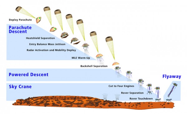
หลังจากเดินทางมุ่งหน้าไปยังดาวอังคารมาแล้วถึง 7 เดือน ตอนนี้ก็เหลือเวลาอีกเพียงไม่ถึงเดือนที่หุ่นยนต์สำรวจดาวอังคาร Curiosity ที่เดินทางไปกับจรวด Atlas V จะเดินทางถึง Gale Crater จุดหมายของมัน และเริ่มทำการสำรวจ ซึ่งมีวัตถุประสงค์ที่ต้องการศึกษาว่าสภาพแวดล้อมบนอังคารทั้งในอดีต และปัจจุบัน สามารถเกื้อหนุนให้มีสิ่งมีชีวิตบนดาวอังคารหรือไม่ แต่อย่างไรก็ตามช่วงเวลาที่อันตรายที่สุดของภารกิจนี้จะเริ่มขึ้นในช่วงเวลา 7 นาทีก่อนที่เจ้า Curiosity จะลงสัมผัสพื้นต่างหาก!
ถึงแม้ว่า Curiosity จะได้รับการออกแบบ และทดสอบเป็นอย่างดีโดยกลุ่มวิศวกรจาก NASA ซึ่งร่วมมือกับบริษัท Boeing และ Lockheed Martin ในการพัฒนา อีกทั้งมีประสบการณ์จากการส่งหุ่นยนต์สำรวจอวกาศคู่แฝด Spirit และ Opportunity มาแล้ว ขั้นตอนการลงจอดของ Curiosity ก็ยังถือว่าเป็นอะไรที่ "สุดโต่ง" มาก ๆ เลยทีเดียว
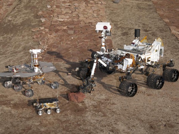
การส่งหุ่นยนต์ขนาดใหญ่อย่าง Curiosity ซึ่งมีขนาดใหญ่พอ ๆ กับรถ mini Cooper หนึ่งคัน มีน้ำหนักมากกว่าเจ้า Spirit และ Opportunity ถึง 5 เท่า ย่อมเป็นอะไรที่ไม่ธรรมดาแน่นอน นาย Bobby Braun อดีต Chief Technologist ของ NASA ได้กล่าวเอาไว้ในเอกสารทางวิชาการในหัวข้อชื่อ Mars Exploration Entry, Descent, and Landing Challenges ว่า ด้วยเทคโนโลยีที่มีอยู่ในปัจจุบัน เราไม่สามารถส่งอะไรที่มีขนาดใหญ่ หรือน้ำหนักที่มากไปกว่านี้ได้อีกแล้ว รวมถึงโครงการที่จะส่งมนุษย์ไปเหยียบดาวอังคารซึ่งต้องบรรทุกสัมภาระไปด้วยเยอะกว่านี้มาก ดังนั้นภารกิจในครั้งนี้ก็ถือเป็นจุด "สุดขีด" ของเทคโนโลยีสำรวจอวกาศในขณะนี้แล้วด้วยนั่นเอง! ความยากลำบากแทบทั้งหมดของภารกิจนี้เป็นผลจากการที่ชั้นบรรยากาศของดาวอังคารที่น้อยกว่าโลกถึง 100 เท่า ทำให้การลดความเร็วเพื่อเข้าสู่พื้นผิวดาวอังคารเป็นไปได้ยากมาก
ด้วยความที่สัญญาณวิทยุที่ส่งจากดาวอังคารต้องใช้เวลาถึง 14 นาทีกว่าจะเดินทางมาถึงโลก ในขณะที่ขั้นตอนการลงจอดทั้งหมด หรือที่เรียกว่า EDL (Enter, Descent, Landing) ใช้เวลาเพียง 7 นาทีเท่านั้น ซึ่งเท่ากับว่า  NASA จะไม่สามารถสื่อสารกับ Curiosity ในขณะที่อยู่ในขั้นตอน EDL ได้เลย กระบวนการทั้งหมดจะต้องทำด้วยระบบอัตโนมัติ และข้อผิดพลาดเพียงเล็กน้อยที่เกิดขึ้นในช่วงเวลาดังกล่าวจะสร้างผลกระทบอย่างรุนแรงต่อภารกิจ  รายละเอียดขั้นตอนการลงจอดจะอธิบายโดยละเอียด แบ่งเป็น 4 ส่วนหลัก ๆ ดังต่อไปนี้ครับ

ขั้นที่ 1 : การเข้าสู่วงโคจร
ในขั้นตอนการลงจอด Curiosity จะบรรจุอยู่ใน aeroshell เกราะกันความร้อนที่เกิดจากการเสียดสีกับชั้นบรรยากาศของดางอังคารที่ความเร็ว 5.3 - 6 กิโลเมตรต่อวินาที หรือประมาณ 19,080 - 21,600 กิโลเมตรต่อชั่วโมง ทำให้เกิดความร้อนสูงถึง 871 องศาเซสเซียส ที่ผิวภายนอก เทคโนโลยี aeroshell นี้ถือว่าเป็นเทคโนโลยีที่ใช้กันมาตั้งแต่ NASA ส่งหุ่นยนต์สำรวจดาวอังคารตัวแรก Viking  (รูปที่ 10 จากเอกสารทางวิชาการ ของนาย Bobby Braun) โดย aeroshell ที่ใช้ในภารกิจนี้มีขนาดใหญ่ที่สุดเท่าที่เคยสร้างมาเช่นกัน  การแก้ไขเส้นทางการลงจอดที่ผิดพลาดไปเนื่องจากการเสียดสีกับชั้นบรรยากาศอย่างรุนแรงในขั้นตอนนี้ จะใช้ไอพ่นขนาดเล็ก (reaction control system) จำนวนสี่ตัวที่ติดอยู่รอบ aeroshell ในการเปลี่ยนทิศทางของแรงยกที่เกิดจาก aeroshell เอง ให้ไปในตำแหน่งลงจอดตามต้องการ

หลังจากขั้นตอนนี้ ชิ้นส่วนที่เป็นฉนวนกันความร้อนด้านหน้าที่อยู่ด้านหน้าของ aeroshell จะถูกปลดออก และมีความเร็วลดลงเหลือเพียงสองเท่าของความเร็วเสียง หรือประมาณ 680 กิโลเมตรต่อชั่วโมง และอยู่สูงจากพื้นผิวดาวอังคาร 10 กิโลเมตร

ขั้นที่ 2 : ปล่อยร่มชูชีพอีกครั้งหนึ่งที่ขนาด และน้ำหนักของ Curiosity ได้เข้ามาทำให้การปล่อยร่มชูชีพเพื่อชะลอความเร็วลงไปอีกมีความยุ่งยากมากขึ้น  ในภารกิจที่ผ่านมาน้ำหนักของหุ่นยนต์ (Viking, Spirit, Opportunity) มีน้ำหนักน้อยกว่ามาก ทำให้ร่มชูชีพช่วยลดความเร็วก่อนที่จะลงสู่พื้นผิวได้  แต่สำหรับ Curiosity ที่มีน้ำหนักมากกว่า Opportunity ถึง 5 เท่าทำให้ร่มชูชีพที่ใช้ต้องมีขนาดใหญ่เป็นพิเศษ ถ้าจะใช้ร่มชูชีพที่ใช้เทคโนโลยีแบบเดียวกันกับภารกิจก่อนหน้านี้ ร่มชูชีพของ Curiosity อาจจะต้องมีขนาดใหญ่ถึง 19.7 เมตร มากกว่าสองเท่าที่ใช้ในภารกิจ MER (Mars Exploration Rover, Spirit และ Opportunity) ที่ใช้ร่มชูชีพขนาด 8.9 เมตร  นอกจากนี้ร่มชูชีพแบบดังกล่าวได้รับการทดสอบถึงความเร็วที่ 1.8 เท่าของความเร็วเสียงเท่านั้น (ใช้งานจริงที่ 1.2 เท่าของความเร็วเสียง) สรุปก็คือ ด้วยเทคโนโลยีเก่านี้ NASA จะต้องใช้ร่มชูชีพที่ใหญ่กว่าเดิมมาก และเริ่มการปล่อยร่มชูชีพที่ระดับต่ำกว่าเดิม (เพราะต้องปล่อยตอนที่ความเร็วจากขั้นตอนแรกลดลงถึง 1.8 เท่าของความเร็วเสียง แทนที่จะเป็น 2.0 เท่า) ซึ่งจะเพิ่มความซับซ้อน และความเสี่ยงของภารกิจมากขึ้นไปอีก

NASA จึงร่วมมือกับบริษัท ILC Dover เพื่อพัฒนาร่มชูชีพที่ใช้เทคโนโลยี IAD (Inflatable Aerodynamic Decelerator) ซึ่งต่างจากวัสดุของร่มชูชีพธรรมดาที่เป็นฟิล์มบาง ที่อุปกรณ์ IAD นี้จะแข็งตัวเมื่อกางออก มีความทนทานและแข็งแรงพอที่จะทนความร้อนของขั้นตอนการลงจอดในส่วนนี้ได้ โดยอุปกรณ์ที่นำมาใช้ในภารกิจนี้จะเป็นเทคโนโลยีที่เรียกว่า SIAD (Supersonic Inflatable Aerodynamic Decelerator) เพราะสามารถที่จะใช้งานที่ความเร็วสูงสุดที่ 2.2 เท่าของความเร็วของเสียงได้ นอกจากนี้ขนาดของร่มชูชีพก็จะสามารถลดขนาดลงเหลือเพียง 16 เมตร เท่านั้น ขณะที่ร่มกาง aeroshell จะต้องรับแรงกระแทกที่มากถึง 9 เท่าของแรงดึงดูดโลก ก่อนที่จะเริ่มสำรวจพื้นผิวดาวอังคารเพื่อยืนยันจุดลงจอดโดยใช้อุปกรณ์เรดาร์ สแกนด้วยความถี่ 5 เฟรมต่อวินาที ที่ระดับความสูงตั้งแต่ 3.7 กิโลเมตรจากพื้นผิว เป็นระยะเวลาสองนาที

ขั้นที่ 3 : ลดความเร็วโดยใช้จรวดขับดันตอนนี้ความเร็วของ Curiosity ลดเหลือเพียง 6 กิโลเมตรต่อวินาที ที่ความสูง 1.8 กิโลเมตร แต่ความเร็วก็ยังสูงเกินไปสำหรับการลงจอด ในขั้นตอนนี้ aeroshell จะถูกปลดออก เหลือเพียงอุปกรณ์ช่วยลงจอดที่ติดอยู่กับ Curiosity ซึ่งประกอบด้วยจรวดขับดัน 8 ตัวที่ใช้ชื่อว่า Mars Landing Engine (MLE)  แต่ละตัวสามารถให้แรงขับตั้งแต่ 400 ถึง 3,100 นิวตัน ช่วยลดความเร็วของ Curiosity ลงจนอยู่ในระดับความเร็วที่มันสามารถควบคุมทิศทางได้ ในขณะที่มันลอยอยู่นั้นมันก็จะเริ่มหย่อน Curiosity ที่ตอนนี้ได้เปลี่ยนจากท่าทางที่มันคุดคู้อยู่ใน aeroshell มาอยู่ในท่าที่เตรียมจะลงสัมผัสกับพื้นผิวดาวอังคารแล้ว

ขั้นที่ 4 : การลงสัมผัสพื้นด้วยลักษณะของ Curiosity ที่ถูกห้อยลงมาจากอุปกรณ์ช่วยลงจอดที่กำลังลอยตัวอยู่ทำให้ อุปกรณ์ช่วยลงจอดในขั้นตอนนี้ถูกเรียกว่า Sky Crane หรือ "ปั้นจั่นลอยฟ้า" นั่นเอง ในขั้นตอนนี้ Sky Crane ยังทำหน้าที่แก้ไขความผิดพลาดของตำแหน่งลงจอดให้น้อยที่อยู่  เมื่อถึงตำแหน่งที่สามารถลงจอดได้แล้ว Sky Crane จะลดระดับความสูงลงเหลือประมาณ 7.5 เมตร และเริ่มหย่อน Curiosity ลงจนสัมผัสพื้น หลังจากที่ Curiosity ได้ส่งคำสั่งยืนยันว่าตัวมันได้ลงถึงพื้นแล้ว Sky Crane จะรออยู่อีกประมาณ 2 วินาที ก่อนที่มันจะตัดสายที่ใช้หย่อน Curiosity ลงมา และสายส่งสัญญาณอื่น ๆ ออกโดยใช้อุปกรณ์ pyro ซึ่งเป็นวัตถุระเบิดขนาดเล็ก ก่อนที่จะบอกลา และบินออกไปให้ไกลจาก Curiosity ให้ได้มากที่สุดเพื่อความปลอดภัย

หลังจากขั้นตอนนี้ Curiosity ก็อยู่บนพื้นผิวดาวอังคารและพร้อมที่จะสำรวจสภาพแวดล้อมของดาวอังคาร เพื่อวิเคราะห์ว่าสภาพแวดล้อมทั้งในอดีต และปัจจุบันของดาวอังคารสามารถเกื้อหนุนสิ่งมีชีวิตได้หรือไม่ และยังเป็นการเก็บข้อมูลเพื่อที่จะเตรียมความพร้อมสำหรับภารกิจการส่งมนุษย์ไปเหยียบพื้นผิวดาวอังคารในอนาคตอีกด้วย

แม้ว่านี่ไม่ใช่ครั้งแรกที่ NASA จะส่งหุ่นยนต์ไปถึงดาวอังคาร อีกทั้งระบบ และอุปกรณ์หลาย ๆ อย่างที่ใช้ในภารกิจนี้ก็พัฒนาต่อขึ้นมาจากสมัยของภารกิจ Viking แต่ระบบ Sky Crane นี้เป็นระบบที่ไม่เคยมีการใช้งานจริงมาก่อนและกำลังจะได้รับการพิสูจน์ในอีกไม่กี่วันข้างหน้านี้แล้ว

เพื่อความไม่สับสน ตามไปดู clip video อธิบายขั้นตอนการลงจอดแบบ animation กันเลยดีกว่าครับ


อ้างอิง :
Wired Science : Landing on Mars
NASA : NASA news

Friday, June 15, 2012

Raspberry Pi! anyone?

I just got my long awaited Raspberry Pi, super small and cheap computer, from element14 at S$48. The Pi equipped with everything you will need for typical computer, USB, Ethernet port, HDMI, SD card slot and audio output.


List of additional hardware:

  • HDMI - to - DVI cable : because my monitor not support HDMI :(
  • USB with external powered hub : I plan to use WiFi- USB device later which power supply from USB alone is not enought.
  • SDHC (hi-speed SD card) class 6 : from information I can find, the Pi only support SD or SDHC card, not micro-SC card with adapter, with class 4 or more (speed issue I guess?).
This three item cost me about S$82, hope I can learn a lot from it. Let's try ...

First, prepare your SD card

I used the "Easy way" from this link which in short include just two step. First, download Win32DiskImager which is a tool to copy your image file (will get to this in step 2) into your SD card. Step two, download image file, the Debain "squeeze" is recommended one.

Two, connect your hardware

Next obvious step is to connect a required hardware - keyboard, mouse, screen and SD card (you prepared in the first step). For power port, I use my phone charger which luckily a micro USB and provide 1A maximum. Power from USB port alone is not enough for the Pi because its need 700mA while USB 2.0 can provide 0.5A maximum.


Last step, hold your breadth and power it up

When you plugged power cord in you will see a red and green LED onbord the Pi start to blink and (hopefully) your screen flushing with output like this,


And after awhile, it will ask you to input login name (default: pi) and password (default: raspberry). When that's done, you are ready to go! use command "startx" to launch an X window system and you got this


Hoorey! you just got yourself a brand new tool to learn lots of new things!

Tuesday, June 5, 2012

LabView diagram for H-bridge control

Well, after wiring all the cable it's time for programming! My tools of choices for this quick jobs is LabView from National Instrument.

Setting up serial communication in LabView can be done using just 4 block, Open port, Send data, Receive data and Close port. Put everything in While-loop adds a few button and even-case and we are good to go!

My code is shown below :


Well, what the point of seeing my code? would it be nice if you can just copy + past and run above code without having to drag and drop everything yourself? Here is another thing I love about LabView, you can just copy above picture (it is .png file) then open your newly open LabView windows and drop the picture on the window, then tada~~~ there is a ready to run VI for you.

Some useful tip
Do not change direction of your motor abruptly, stop a motor first then change. This is to prevent current surge in your circuit especially when you don't have any current protection circuit like mine!

Warning!
Before connect your motor to power source, it would be wise to test the H-bridge circuit first! Relay of the same side must not close (current able to pass through) at the same time, otherwise current will pass from source (say 24Volt.) directly to Ground which will burn all of your cables and relays.

Quick jobs : H-Bridge circuit to drive a motor

To day my supervisor just pop in and throw me 8 solid-state-relay (SSR) and ADAM-4068 (Serial-I/O device) and ask me to wire a circuit to control a motor for his robot.

ADAM-6048 is a handy device that let you control digital input and output via RS-485, serial communication given a protocol in its manual. Output of ADAM is rated at 0.5 ampere so I use it to control the SSR which can operate up to 40 ampere each.

Circuit diagram is as follow, bigger line means high current cable :


Note :
RL0 NO -- Relay channel 0 of ADAM, Normally Open pin
RL0 COM -- Relay channel 0 of ADAM, Common pin

When output set to "high", current will able to flow from COM to NO. Best to imagine it as a simple switch, when push both pin will connect and let a current flowing. Then pin 1 and pin 2 of SSR will connect and let a (high) current pass through the motor.

Warning!
Unlike normal relay, SSR let current pass in only one direction, from pin 2 to pin 1 and from pin 4 to pin 3 as I indicate + and - sign in above diagram. I blown 2 SSR because of this ignorance!


SSR I'm using are Maxwell's MS-DD6040.

Sunday, June 3, 2012

Getting start with ROSARIA

After get ROS installed, let's get ARIA working. ARIA is an open-source software to communicate with ACOS (low-level control of our Pioneer3-AT). ROSARIA is name of ARIA package in ROS.

I came across this post about how to get ROSARIA install,
http://answers.ros.org/question/11962/require-help-using-rosaria/

I follow the recommended answer and got ROSARIA install successfully. There are some points that I would remind you, before you install the package as mentioned in the post you should go to your working folder first. If you follow the ROS tutorial as I recommended, your working folder is the "ros_workspace" folder in "home" directory. After ROSARIA package is installed, make sure you don't miss the "rosmake" part!, you will get folder "hg" in "ros_workspace".

Also note that the "teleop_base" path will not work as it is no longer support in ROS Electric, but don't worries we will talk about it later.

When everything is ready, let's try it out!

Step1: Safety first!

The most important thing in working with everything with moving part is safety! Take a look around and grab anything that can fit underneath your bot's belly to lift it up, all the wheels should not contact the ground and move freely. This is important because we don't know what gonna happen after we powered our robot for the first time or after we run a new piece of code.

Step2 : Connect to the robot

Now that your robot hang helplessly above ground it's a time to bring it to life! Get you RS-232 ready and plug it to the Pioneer DB9 socket, then plug another end to your computer (of course). Then power your bot up and release the emergency switch (the red button switch).

Step3 : First contact

First thing first, you need to figure out which communication port you are using. ROSARIA default value of port is ttyUSB0, for those USB-to-Serial converter. In my case it's old-school serial port ttyS0.

Bring up you terminal and go to your ROS workspace folder.
$ cd ros_workspace 

In first terminal, bring ROS up to work
$ roscore 

Leave the first terminal untouch and open another terminal and go to your workspace again, now run.
$ rosrun ROSARIA RosAria _port:=/dev/ttyS0

In above code, you may change the "/dev/ttyS0" part to your connected port such as "/dev/ttyUSB0", "/dev/ttyUSB1" or "/dev/ttyS1".

When you press enter, your robot should make a beep-beep sound and have something show-up in your terminal.

Congratulation! you just bring your robot up to life for the first time!


Installing ROS

When you got Ubuntu running then installing ROS is very simple, even for those who never use Ubuntu and never deal with command line before. All you need to do in to launch a terminal up and copy&paste a few command (then press 'Enter'!) from installation instruction from this link.

Note that you can't use ctrl+v and ctrl+c shortcut-key in termical, you can use shift+ctrl+v and shift+ctrl+c or mouse-right-click then paste and mouse-right-click then copy instead.

After follow all the steps, which will take you sometime to download and setup, I would highly recommend you to follow a tutorials, especially the first one  installing and configuring you ROS environment, in order to make sense of how ROS work, how to use it and some special terms that you will need to known in order to change and modify a code.

The whole tutorials take me just a couple of days to finish and its cover all the fundamentals topics I need for the project.

Note
In case of you can not find how to bring up a terminal -> http://www.psychocats.net/ubuntu/terminal.

Start using ROS!

I would like to make a document of how I implement ROS framework on my robot. Everything I wrote here are working in progress, it's the way I do but not proven, which should be good enough as a guidance to get you up and running faster.


Let's start from what I have in hand.

Hardware


Robot platform : Pioneer3-AT


  • My lab bought this guy without any on-board computer and additional sensors. It does come with low-level controller, called ARCOS, which later we will communicate with it vai RS-232 port. The robot also come with wheel encoder and basic PID velocity control, so at the end of the day we just send our desired speed to ARCOS to make it move.
  • To communicate with ARCOS, Pioneer is shipped with open-source SDK called ARIA which provide an interface for controlling and receiving data from all Pioneers platform.

Software

  • Because the robot didn't come with on-board computer, I will put a computer on top of it. The computer run the following software.
    • Linux Ubuntu : Ubuntu 11.10 (32-bits) - Oneiric Ocelot. It's the latest Ubuntu version at the beginning of this project, at the time of writing this post there is version 12, but that's not matter anyways.
    • ROS :  ROS Electric. We're going to learn a good deal about this ROS!