You know something went wrong when things goes too smoothly. After flash the board for a few time to fix WiFi driver and install ROS Indigo my screen black out went I try to reboot it. Screen show streams of text while booting, then Nvidia logo show up and then went blank after that.
Don't to flash it once again, I search some more and found that I am not the only one and this (luckily). Problem, figure out by this guy, is that file libglx.so being replace by some update or process causing the board can't display properly. The fix is easy, go back to your host computer's download folder where you download Tegra124_Linux_R19.3.0_armhf.tbz2 package when to prepare to compile The Grinch kernel.
Unpack Tegra124_Linux_R19.3.0_armhf.tbz2
You we get Linux_for_Tegra folder.
Find Linux_for_Tegra/nv_tegra/nvidia_drivers.tbz2 and unpack it.
Navigate to usr/lib/xorg/modules/extensions/ there you will have the original libglx.so file.
Copy the original libglx.so file from host computer to the TK1 board, place it in the same usr/lib/xorg/modules/extensions/ folder. You may backup the TK1's libglx.so file first by change its name to something like libglx.so.bak
Cross your finger and reboot.
If you boot into Ubuntu GUI screen then you're done! better to keep the new libglx.so file just in case we need it again. By copy and rename it to libglx.so.original.
I hope all the smart guys at Nvidia will figure out the cause and way to get around this soon.
The problem is that after I move to The Grinch kernel and do some update & upgrade I can't reboot back to the Ubuntu screen. I tried ssh into it and its seem to working just fine. No choice, I decided to flash the board again, but I got a message "flash fail" and hence process to follow the Hint #1. After 2 times of flashing the board, problem still persist.
I then try to undo the Hint #1 by (follow this link for instructions)
remove
losetup --find --show system.img
And replace with
losetup /dev/loop0 system.img >/dev/null2>&1
And flash it one more time. This time I able to update & upgrade and install ROS indigo (for ARM, bare-bone package) while able to reboot back to Ubuntu screen.
PS: I also tried to install ROS Indigo from source, which went fine, but actually someone (up there?) make an installation for Ubuntu-ARM architecture already, you can follow a link here.
Things went too smoothly, what else can go wrong? ... my Ubuntu screen gone again :(
I recently got this new, cheap development from Nvidia called Jetson Tk1. The main highlight of these board is that its contain 192 GPU core inside. Unlike another microcomputer board like Raspberry Pi or BeagleBone black, TK1 is able to run Ubuntu 14.04 (ARM version) with decent graphic and response.
I got my board from newEgg website for around 300 SGD, for some reason you cannot buy the board from Nvidia's website if you are not in the US.
First boot-up went fine, just plug-in the 12 volt power supply that come with the board and it will boot into command-line screen. There you will see Nvidia driver install script, just execute that and it will restart and land you to Ubuntu's GUI screen.
Unfortunately, the kernel that chipped with TK1 (at least the one I got) doesn't support WiFi dongle. Searching around the web gave me 2 options.
Option 1:
Download RTL8192CU here and follow the procedure in comment #9 to include the driver into current kernel.
Option 2:
Follow an instruction from Nvidia development forum to upgrade kernel to The Grinch which added support for Wifi dongle and many more device.
I don't think totally wipe out an original kernel (option 2) since day 1 is not a very good idea, so I go for option 1, which went smoothly. After reboot the TK1 detect my WiFi dongle and able to connect to WiFi network with ease of Network manager with GUI.
After a while (like 10 minutes) I thought move on to The Grinch (option 2) might be a better ideal because I am planing to install ROS and OpenCV onto it, upgrade a kernel after will not be so easy.
Some commonly missing step after install arduino IDE is forget to add yourself into "dialout" and "tty" group. You can do so by the following command.
$sudo usermod -a -G tty yourUserName
and
$sudo usermod -a -G dialout yourUserName
To use rosserial, after you have done everything in the rosserial's tutorial and try to complie (or verify) your code you might got an error message like the following :
In file included from /Users/kevin/Documents/Arduino/libraries/ros_lib/ros.h:39, from HelloWorld.cpp:6: /Users/kevin/Documents/Arduino/libraries/ros_lib/ArduinoHardware.h:38:22: error: WProgram.h: No such file or directory
You fix it by go to the mentioned file, in this case, located at "/Users/kevin/Documents/Arduino/libraries/ros_lib/"
$cd /Users/kevin/Documents/Arduino/libraries/ros_lib/ $gedit ArduinoHardware.h Replace the line "#include WProgram.h" with the following #if defined(ARDUINO) && ARDUINO >= 100 #include "Arduino.h" #else #include "WProgram.h" #endif
Go back to the IDE and compile the code again, and it should be fine.
Canon-Europe website provide Linux driver for Canon iRC2380i printer. Just download CQue 2.0.5 Linux Driver DEB (32 bits or 64 bits version, depend on your machine) from the link. After download, double-click on the DEB file and Ubuntu Software Center should come up and you can install it from there.
After driver is installed successfully, go to System Settings -> Printing -> Add -> Click on Network Printer and wait for a while. Canon C2380/2550 should be on the list and you are done.
However, SMART need to set up a department account (department ID and password) to protect the printer from unauthorized users. Unfortunately, the driver doesn’t support department account directly from GUI. The following guide will show how to do just that.
After you install the CQue Linux driver as mentioned above, you should have PPD folder locate at /opt/cel/ppd.
In terminal
$cd /opt/cel/ppd
$ls
Here you will see a long list of supported drivers, our Canon iRC2380i’s driver is named “cel-irc1028-pcl-en.ppd.gz” we need to unzip (using gzip) and modify it.
still in the /opt/cel/ppd folder
$gzip -d cel-irc1028-pcl-en.ppd.gz
Now you should have unziped file named “cel-irc2380-pcl-en.ppd” which we need to modify.
$sudo gedit cel-irc2380-pcl-en.ppd
Locate a line similar to (you can use find function (Ctrl+f) in gedit to find this line)
*NickName: "Canon iR C2380/2550 PCL
And modify it to
*NickName: "Canon iR C2380/2550 PCL SMART”
And also locate line
*ShortNickName: "Canon iR C2380/2550 PCL"
And modify it to
*ShortNickName: "Canon iR C2380/2550 PCL SMART"
Next locate line
*DefaultUserID: None
And modify “None” to your department’s ID, for example
*DefaultUserID: 12345
Last Locate line
*DefaultUserPassword: None
And modify “None” to your department’s password, for example
*DefaultUserPassword: 6789
You are done! Save the file and exit.
Back to System Settings -> Printing you should see the Canon iRC2380i icon there. Right-click -> Properties -> Settings -> Make and Model -> Change -> Choose “Provide PPD file” -> on the sidebar click on “File system” -> opt -> cel -> ppd -> chose the cel-irc2380-pcl-en.ppd we just edited. -> Select option “Use the new PPD … as is”
Now you will be back to Printer Properties window, in Settings you should see the Make and Model field is now write “Canon iR C2380/2550 PCL SMART”, which indicate that the printer are now using the PPD file we just edited.
There are many kind of script out there,but this is what suite me best. The script limit a command prompt to 30 character, if longer than that its will show only the first 12 and last 15 characters. The "\h" in the last line is added to show a hostname, convenient if you often work on remote machine.
To use, just put the following text in ./bashrc file.
#--- Custom terminal, cutout lengthly word ---
PROMPT_COMMAND='DIR=`pwd|sed -e "s!$HOME!~!"`; if [ ${#DIR} -gt 30 ]; then CurDir=${DIR:0:12}...${DIR:${#DIR}-15}; else CurDir=$DIR; fi'
To make life a bit easier a backup script
is attached here (at the end of this page) to make a full-system backup.
The script will do the following:
It will empty your trash.
make
an list of files and folder that to don't want to backup (an
exclude_file mentioned as above). Files ended with .bag, .mpg, .mpeg,
.avi, .png will be exclude and also everything in /tmp and /download
folder.
then it will create a destination folder at your argument directory.
Usage of the script chmod +x fullbackup.sh and then (assumed that you want to put a backup file at /home/golfcar) ./fullbackup /home/golfcar After backup finish, you will see a folder named likegolfcart-master-010313.tgz where "golfcart-master" is your hostname and "010313"is a backup date (01/03/2013). The script can be download from here
Iwas looking for the way to cluster a points, grouping a neighbourhood points together, but since I don't know number clusters in the data and therefore the k-mean clustering can't be use. After do some search on Google and our good friend Wikipedia I come across this alternative clustering algorithm.
DBSCAN is short from Density-Based Spatial Clustering of Application with Noise (reference from wiki : DBSCAN) Explanation in plain english DBSCAN requires two parameters:
(eps) and the minimum number of points required to form a cluster
(minPts). It starts with an arbitrary starting point that has not been
visited. This point's -neighborhood
is retrieved, and if it contains sufficiently many points, a cluster is
started. Otherwise, the point is labeled as noise. Note that this point
might later be found in a sufficiently sized -environment of a different point and hence be made part of a cluster. If a point is found to be a dense part of a cluster, its -neighborhood is also part of that cluster. Hence, all points that are found within the -neighborhood are added, as is their own -neighborhood
when they are also dense. This process continues until the
density-connected cluster is completely found. Then, a new unvisited
point is retrieved and processed, leading to the discovery of a further
cluster or noise. Here is a code in Python
#! /usr/bin/python
from math import sqrt, pow
class DBSCAN:
#Density-Based Spatial Clustering of Application with Noise -> http://en.wikipedia.org/wiki/DBSCAN
def __init__(self):
self.name = 'DBSCAN'
self.DB = [] #Database
self.esp = 4 #neighborhood distance for search
self.MinPts = 2 #minimum number of points required to form a cluster
self.cluster_inx = -1
self.cluster = []
def DBSCAN(self):
for i in range(len(self.DB)):
p_tmp = self.DB[i]
if (not p_tmp.visited):
#for each unvisited point P in dataset
p_tmp.visited = True
NeighborPts = self.regionQuery(p_tmp)
if(len(NeighborPts) < self.MinPts):
#that point is a noise
p_tmp.isnoise = True
print p_tmp.show(), 'is a noise'
else:
self.cluster.append([])
self.cluster_inx = self.cluster_inx + 1
self.expandCluster(p_tmp, NeighborPts)
def expandCluster(self, P, neighbor_points):
self.cluster[self.cluster_inx].append(P)
iterator = iter(neighbor_points)
while True:
try:
npoint_tmp = iterator.next()
except StopIteration:
# StopIteration exception is raised after last element
break
if (not npoint_tmp.visited):
#for each point P' in NeighborPts
npoint_tmp.visited = True
NeighborPts_ = self.regionQuery(npoint_tmp)
if (len(NeighborPts_) >= self.MinPts):
for j in range(len(NeighborPts_)):
neighbor_points.append(NeighborPts_[j])
if (not self.checkMembership(npoint_tmp)):
#if P' is not yet member of any cluster
self.cluster[self.cluster_inx].append(npoint_tmp)
else:
print npoint_tmp.show(), 'is belonged to some cluster'
def checkMembership(self, P):
#will return True if point is belonged to some cluster
ismember = False
for i in range(len(self.cluster)):
for j in range(len(self.cluster[i])):
if (P.x == self.cluster[i][j].x and P.y == self.cluster[i][j].y):
ismember = True
return ismember
def regionQuery(self, P):
#return all points within P's eps-neighborhood, except itself
pointInRegion = []
for i in range(len(self.DB)):
p_tmp = self.DB[i]
if (self.dist(P, p_tmp) < self.esp and P.x != p_tmp.x and P.y != p_tmp.y):
pointInRegion.append(p_tmp)
return pointInRegion
def dist(self, p1, p2):
#return distance between two point
dx = (p1.x - p2.x)
dy = (p1.y - p2.y)
return sqrt(pow(dx,2) + pow(dy,2))
class Point:
def __init__(self, x = 0, y = 0, visited = False, isnoise = False):
self.x = x
self.y = y
self.visited = False
self.isnoise = False
def show(self):
return self.x, self.y
if __name__=='__main__':
#this is a mocking data just for test
vecPoint = [Point(11,3), Point(10,4), Point(11,5), Point(12,4), Point(13,5), Point(12,6), Point(6,10), Point(8,10), Point(5,12), Point(7,12)]
#Create object
dbScan = DBSCAN()
#Load data into object
dbScan.DB = vecPoint;
#Do clustering
dbScan.DBSCAN()
#Show result cluster
for i in range(len(dbScan.cluster)):
print 'Cluster: ', i
for j in range(len(dbScan.cluster[i])):
print dbScan.cluster[i][j].show()
I have come across this site showing guide on ROS installation made easy, which really made it easy with step-by-step to install ROS. Should be very useful for anyone who looking for a "sure way" to install ROS on Ubuntu.
There site also have many interesting articles as well!
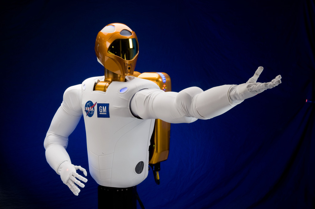
āļัāļ§āļāļĒ่āļēāļāļŦāļึ่āļāļāļāļāļŦุ่āļāļĒāļāļ์āļี่āļāļģāļāļēāļāđāļีāļĒāļāļ้āļēāļāđāļĨāļ°āļāļāļĒāļ่āļ§āļĒāđāļŦāļĨืāļāļĄāļุāļĐāļĒ์āđāļāļāļ§āļāļēāļĻāļ็āļืāļ Robonaut āļŦุ่āļāļĒāļāļ์āļāļĨ้āļēāļĒāļĄāļุāļĐāļĒ์āļี่āļĄีāļĢ่āļēāļāļāļēāļĒāđāļ่āļŠ่āļ§āļāļāļāļāļāļ NASA āđāļ็āļāļŦุ่āļāļĒāļāļ์āļึ่āļāļัāļāđāļ็āļāļŦāļึ่āļāđāļāļŠāļĄāļēāļิāļāļāļāļŠāļāļēāļีāļāļ§āļāļēāļĻāļāļēāļāļēāļāļēāļิāļี่āđāļ้āļĢัāļāļāļēāļĢāļāļāļŠāļāļāļāļēāļĢāđāļ้āļāļēāļāļāļĢิāļ āđāļĨāļ°āđāļĢิ่āļĄāļ่āļ§āļĒāđāļŦāļĨืāļāļāļēāļĢāļāļģāļāļēāļāļāļāļāļัāļāļิāļāļāļ§āļāļēāļĻāđāļĨ้āļ§ āļāļģāđāļŦ้āļัāļāļิāļāļāļ§āļāļēāļĻāļĄีāđāļ§āļĨāļēāļี่āļāļ°āļāļģāđāļāđāļ้āļัāļāļāļēāļāđāļāļŦ้āļāļāļāļāļĨāļāļāļึ่āļāļĄีāļāļ§āļēāļĄāļัāļāļ้āļāļāđāļĨāļ°āļŠāļģāļัāļāļāļ§่āļēāļāļēāļāļึ้āļ
āļุāļāļĄุ่āļāļŦāļĄāļēāļĒāļāļāļ NASA āļี่āļ้āļāļāļāļēāļĢāļัāļāļāļēāļีāļāļāļ§āļēāļĄāļŠāļēāļĄāļēāļĢāļāļāļāļāļŦุ่āļāļĒāļāļ์āļั้āļāļ็āđāļื่āļāļ้āļāļāļāļēāļĢāđāļŦ้āļŦุ่āļāļĒāļāļ์āļŠāļēāļĄāļēāļĢāļāļāļģāļāļēāļāđāļีāļĒāļāļ้āļēāļāļัāļāļĄāļุāļĐāļĒ์āļั้āļāļāļāđāļĨāļāđāļĨāļ°āđāļāļāļ§āļāļēāļĻ āļึ่āļāļāļ°āļāļģāđāļŦ้āļĄāļุāļĐāļĒ์āļāļģāļāļēāļāđāļ้āļāļĒ่āļēāļāļĄีāļāļĢāļ°āļŠิāļāļิāļ āļēāļāļŠูāļāļŠุāļ āļĨāļāļ้āļāļāļģāļัāļāļ้āļēāļāļāļ§āļēāļĄāļŠāļēāļĄāļēāļĢāļāļāļāļāļĄāļุāļĐāļĒ์ āđāļĨāļ°āļāļĢัāļāļāļĢุāļāđāļĢื่āļāļāļāļ§āļēāļĄāļāļĨāļāļāļ ัāļĒāđāļāļāļēāļĢāļāļģāļāļēāļāđāļŦ้āļĄāļēāļāļึ้āļ
āļĢāļēāļĒāļื่āļ 8 āđāļāļĢāđāļāļāļ์āļี่āđāļ้āļĢัāļāļāļēāļĢāļŠāļัāļāļŠāļุāļāđāļāļĒ NASA āļĄีāļัāļāļ่āļāđāļāļี้
āļŦุ่āļāļĒāļāļ์āļāļ§āļāļēāļĢ (āļŦุ่āļāļĒāļāļ์āļี่āđāļāļĨื่āļāļāđāļŦāļ§āļāļēāļĄāļĄāļุāļĐāļĒ์āļู้āļāļ§āļāļุāļĄāļĢāļ°āļĒāļ°āđāļāļĨ), ”Toward Human Avatar Robots for Co-Exploration of Hazardous Environments,” J. Pratt, principal investigator, Florida Institute of Human Machine Cognition, Pensacola
āļĢāļ°āļāļāļāļēāđāļีāļĒāļĄ, ”A Novel Powered Leg Prosthesis Simulator for Sensing and Control Development,” H. Herr, principal investigator, Massachusetts Institute of Technology, Cambridge
āļĢāļ°āļāļāļāļģāļāļēāļĒāļĨัāļāļĐāļāļ°āļื้āļāļิāļ§āļี่āļĄีāļāļ§āļēāļĄāļัāļāļāļĢāļēāļĒāļ่āļāļŦุ่āļāļĒāļāļ์āļŠāļģāļĢāļ§āļ, “Long-range Prediction of Non-Geometric Terrain Hazards for Reliable Planetary Rover Traverse,” R. Whittaker, principal investigator, Carnegie Mellon University, Pittsburgh
āļิāļ§āļāļģāļĨāļāļāļี่āļĄีāļāļ§āļēāļĄāļŠāļēāļĄāļēāļĢāļāđāļāļāļēāļĢāļĢัāļāļĢู้āļŠāļģāļŦāļĢัāļāļŦุ่āļāļĒāļāļ์, ”Active Skins for Simplified Tactile Feedback in Robotics,” S. Bergbreiter, principal investigator, University of Maryland, College Park
āļĢāļ°āļāļāļŠ่āļāļāļģāļĨัāļāļŠāļģāļŦāļĢัāļāļŦุ่āļāļĒāļāļ์āđāļŠāļĄืāļāļāļĄāļุāļĐāļĒ์, “Actuators for Safe, Strong and Efficient Humanoid Robots,” S. Pekarek, principal investigator, Purdue University
āļĢāļ°āļāļāļāļ§āļāļุāļĄāļŦุ่āļāļĒāļāļ์āļĢāļ°āļĒāļ°āđāļāļĨ, ”Whole-body Telemanipulation of the Dreamer Humanoid Robot on Rough Terrains Using Hand Exoskeleton (EXODREAM),” L. Sentis, principal investigator, University of Texas at Austin
āļŦุ่āļāļĒāļāļ์āđāļāļāļāļēāļ āđ āļĒāļēāļ§ āđ, ”Long, Thin Continuum Robots for Space Applications,” I. Walker, principal investigator, Clemson University, Clemson, S.C.
āļĢāļ°āļāļāļāļ§āļāļุāļĄāļŠāļģāļŦāļĢัāļāļŦāļĒิāļāļัāļāļ§ัāļāļุāļ่āļāļāļิ่āļĄ, ”Manipulating Flexible Materials Using Sparse Coding,” R. Platt, principal investigator, State University of New York, Buffalo
NASA āļĄีāļāļĢāļ°āļ§ัāļิāļัāļāļĒāļēāļ§āļāļēāļāđāļāļāļēāļĢāļัāļāļāļēāđāļāļāđāļāđāļĨāļĒีāļĨ้āļģāļŠāļĄัāļĒāļŠāļģāļŦāļĢัāļāļāļēāļĢāđāļ้āļāļēāļāđāļāļāļ§āļāļēāļĻ āļāļāļāļāļēāļāļี้ NASA āļĒัāļāđāļ้āļĢ่āļ§āļĄāļĄืāļāļัāļāļ āļēāļāđāļāļāļāļāļ āļēāļĒāđāļāļŠāļŦāļĢัāļāļŊ āļĄāļŦāļēāļ§ิāļāļĒāļēāļĨัāļĒ āđāļĨāļ°āļ āļēāļāļĢัāļāļŊ āđāļāļāļēāļĢāļ่āļēāļĒāļāļāļāđāļāļāđāļāđāļĨāļĒีāđāļŦāļĨ่āļēāļี้āļāļĨัāļāļŠู่āļ āļēāļāļุāļāļŠāļēāļŦāļāļĢāļĢāļĄāļāļāļāļŠāļŦāļĢัāļāļŊ āđāļื่āļāđāļิ่āļĄāļāļ§āļēāļĄāļŠāļēāļĄāļēāļĢāļāļ้āļēāļāļāļēāļĢāļāļĨิāļ āđāļĨāļ°āļāļēāļĢāđāļ่āļāļัāļāļ้āļēāļāđāļĻāļĢāļĐāļāļิāļāļีāļāļ้āļ§āļĒ
āļāļēāļāļ่āļēāļ§āļี้āđāļĢāļēāļāļ°āđāļŦ็āļāđāļ้āļ§่āļē NASA āđāļ้āđāļ้āļāļāļ§āļēāļĄāļŠāļģāļัāļāđāļāļี่āļāļēāļĢāļĢัāļāļĢู้āđāļĨāļ°āļāļēāļĢāļāļ§āļāļุāļĄāļĢāļ°āļĒāļ°āđāļāļĨāļั่āļāđāļāļ
I just setup my work station at my new workplace and found out that my Ubuntu 12.04 with ATI graphic card cannot output dual screen (two 1600x900) with message indicate that it exceed maximum screen size (1600x1600). After doing some search I found a fix.
I have to configure file xorg.conf in ~/etc/X11/ folder by adding subsection "display" part is section "screen" as follow (character in green):
Above code will change maximum size to 3600x3600 larger than what I really want (but it's fine). Save and reboot the system and I can use dual-monitor as I want.
I just got my long awaited Raspberry Pi, super small and cheap computer, from element14 at S$48. The Pi equipped with everything you will need for typical computer, USB, Ethernet port, HDMI, SD card slot and audio output.
List of additional hardware:
HDMI - to - DVI cable : because my monitor not support HDMI :(
USB with external powered hub : I plan to use WiFi- USB device later which power supply from USB alone is not enought.
SDHC (hi-speed SD card) class 6 : from information I can find, the Pi only support SD or SDHC card, not micro-SC card with adapter, with class 4 or more (speed issue I guess?).
This three item cost me about S$82, hope I can learn a lot from it. Let's try ...
First, prepare your SD card
I used the "Easy way" from this link which in short include just two step. First, download Win32DiskImager which is a tool to copy your image file (will get to this in step 2) into your SD card. Step two, download image file, the Debain "squeeze" is recommended one.
Two, connect your hardware
Next obvious step is to connect a required hardware - keyboard, mouse, screen and SD card (you prepared in the first step). For power port, I use my phone charger which luckily a micro USB and provide 1A maximum. Power from USB port alone is not enough for the Pi because its need 700mA while USB 2.0 can provide 0.5A maximum.
Last step, hold your breadth and power it up
When you plugged power cord in you will see a red and green LED onbord the Pi start to blink and (hopefully) your screen flushing with output like this,
And after awhile, it will ask you to input login name (default: pi) and password (default: raspberry). When that's done, you are ready to go! use command "startx" to launch an X window system and you got this
Hoorey! you just got yourself a brand new tool to learn lots of new things!
Tuesday, June 5, 2012
LabView diagram for H-bridge control
Well, after wiring all the cable it's time for programming! My tools of choices for this quick jobs is LabView from National Instrument.
Setting up serial communication in LabView can be done using just 4 block, Open port, Send data, Receive data and Close port. Put everything in While-loop adds a few button and even-case and we are good to go!
My code is shown below :
Well, what the point of seeing my code? would it be nice if you can just copy + past and run above code without having to drag and drop everything yourself? Here is another thing I love about LabView, you can just copy above picture (it is .png file) then open your newly open LabView windows and drop the picture on the window, then tada~~~ there is a ready to run VI for you.
Some useful tip
Do not change direction of your motor abruptly, stop a motor first then change. This is to prevent current surge in your circuit especially when you don't have any current protection circuit like mine!
Warning!
Before connect your motor to power source, it would be wise to test the H-bridge circuit first! Relay of the same side must not close (current able to pass through) at the same time, otherwise current will pass from source (say 24Volt.) directly to Ground which will burn all of your cables and relays.
Quick jobs : H-Bridge circuit to drive a motor
To day my supervisor just pop in and throw me 8 solid-state-relay (SSR) and ADAM-4068 (Serial-I/O device) and ask me to wire a circuit to control a motor for his robot.
ADAM-6048 is a handy device that let you control digital input and output via RS-485, serial communication given a protocol in its manual. Output of ADAM is rated at 0.5 ampere so I use it to control the SSR which can operate up to 40 ampere each.
Circuit diagram is as follow, bigger line means high current cable :
Note :
RL0 NO -- Relay channel 0 of ADAM, Normally Open pin
RL0 COM -- Relay channel 0 of ADAM, Common pin
When output set to "high", current will able to flow from COM to NO. Best to imagine it as a simple switch, when push both pin will connect and let a current flowing. Then pin 1 and pin 2 of SSR will connect and let a (high) current pass through the motor.
Warning!
Unlike normal relay, SSR let current pass in only one direction, from pin 2 to pin 1 and from pin 4 to pin 3 as I indicate + and - sign in above diagram. I blown 2 SSR because of this ignorance!
SSR I'm using are Maxwell's MS-DD6040.
Sunday, June 3, 2012
Getting start with ROSARIA
After get ROS installed, let's get ARIA working. ARIA is an open-source software to communicate with ACOS (low-level control of our Pioneer3-AT). ROSARIA is name of ARIA package in ROS.
I follow the recommended answer and got ROSARIA install successfully. There are some points that I would remind you, before you install the package as mentioned in the post you should go to your working folder first. If you follow the ROS tutorial as I recommended, your working folder is the "ros_workspace" folder in "home" directory. After ROSARIA package is installed, make sure you don't miss the "rosmake" part!, you will get folder "hg" in "ros_workspace".
Also note that the "teleop_base" path will not work as it is no longer support in ROS Electric, but don't worries we will talk about it later.
When everything is ready, let's try it out!
Step1: Safety first!
The most important thing in working with everything with moving part is safety! Take a look around and grab anything that can fit underneath your bot's belly to lift it up, all the wheels should not contact the ground and move freely. This is important because we don't know what gonna happen after we powered our robot for the first time or after we run a new piece of code.
Step2 : Connect to the robot
Now that your robot hang helplessly above ground it's a time to bring it to life! Get you RS-232 ready and plug it to the Pioneer DB9 socket, then plug another end to your computer (of course). Then power your bot up and release the emergency switch (the red button switch).
Step3 : First contact
First thing first, you need to figure out which communication port you are using. ROSARIA default value of port is ttyUSB0, for those USB-to-Serial converter. In my case it's old-school serial port ttyS0.
Bring up you terminal and go to your ROS workspace folder.
$ cd ros_workspace
In first terminal, bring ROS up to work
$ roscore
Leave the first terminal untouch and open another terminal and go to your workspace again, now run.
$ rosrun ROSARIA RosAria _port:=/dev/ttyS0
In above code, you may change the "/dev/ttyS0" part to your connected port such as "/dev/ttyUSB0", "/dev/ttyUSB1" or "/dev/ttyS1".
When you press enter, your robot should make a beep-beep sound and have something show-up in your terminal.
Congratulation! you just bring your robot up to life for the first time!